
 EN
EN



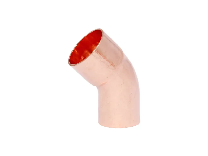
Fluid Dynamics Fundamentals: How Bend Radius Affects Flow in Copper Return Bends
Turbulence, Secondary Flow, and Boundary Layer Separation in Short Radius Configurations
In a copper return bend with a short radius (R/D ≈ 1.0), the fluid undergoes a sharp 180° turn—intensifying curvature-induced forces and triggering pronounced secondary flow. Centripetal acceleration pushes high-velocity core fluid toward the outer wall, establishing a radial pressure gradient that drives slower near-wall fluid inward. This imbalance generates counter-rotating Dean vortices extending downstream, elevating turbulence intensity and distorting the velocity profile. Near the inner wall, the adverse pressure gradient promotes boundary layer separation—especially at Reynolds numbers above 10,000—causing flow detachment and recirculation. The resulting low-momentum zone constricts the effective flow area and amplifies irreversible energy dissipation. Compared to straight pipe, the local friction factor in short-radius bends increases by roughly an order of magnitude. In multi-row heat exchangers where uniform flow distribution is critical, this maldistribution can reduce thermal performance by up to 5% (CFD analysis, 2020). Engineers must therefore weigh spatial constraints against these fluid-dynamic penalties when specifying copper return bends for high-efficiency circuits.
Dean Number Thresholds and the Critical Transition from R = 1.0D to R = 1.5D
The Dean number (De = Re·√(R/D)) governs secondary flow intensity in curved pipes. For a given Reynolds number, De scales inversely with √(R/D); increasing R/D from 1.0 to 1.5 reduces De by ~18%. At R/D = 1.0 and Re = 50,000 (typical for turbulent water flow), De often exceeds 2,500—well above the threshold where strong Dean vortices and persistent inner-wall separation dominate. When R/D rises to 1.5, De falls below ~2,050—the empirically observed critical value for many copper return bend geometries—sharply reducing separation zone size and promoting earlier boundary layer reattachment. CFD benchmarking shows the recirculation length contracts by over 50% near this transition (CFD Benchmark, 2022), yielding a more uniform exit velocity profile and significantly lower irreversible pressure loss. This De-driven shift explains why long-radius copper return bends are essential in high-efficiency HVAC and process piping—where even small reductions in head loss directly improve system efficiency and lifecycle energy use.
Pressure Drop & Energy Loss: Quantifying the Performance Gap Between Short and Long Radius Copper Return Bends
The energy penalty of flow reversal in a copper return bend directly affects operational cost and pump sizing. Tighter curvature intensifies directional change, converting kinetic energy into heat and creating permanent pressure loss the pump must overcome.
CFD-Simulated ΔP Comparison Across 180° Copper Return Bends (R/D = 1.0 vs. 1.5)
CFD simulations isolate geometric effects by removing system-level variables. For standard 180° copper return bends under turbulent flow (Re = 100,000), the pressure drop coefficient (K) of a short-radius bend (R/D = 1.0) is consistently 40–60% higher than that of a long-radius counterpart (R/D = 1.5). This non-linear divergence stems from the severe adverse pressure gradient on the inner wall of the tight bend—triggering early, large-scale separation. The resulting recirculation zone constricts the effective core flow area, forcing accelerated passage through a reduced vena contracta and dissipating energy chaotically. In contrast, the long-radius geometry applies milder centrifugal forcing, sustaining a more uniform velocity profile and delaying separation onset until later in the turn.
| Bend Geometry (180°) | Relative Flow Separation Zone | Normalized Pressure Drop Coefficient (at Re = 1×10⁵) | Energy Dissipation Mechanism |
|---|---|---|---|
| Short Radius (R/D = 1.0) | Large, initiates at ~60° | 2.4 – 2.8 | Massive recirculation & core flow acceleration |
| Long Radius (R/D = 1.5) | Small, initiates at ~90° | 1.6 – 1.8 | Mild secondary flow & gradual velocity restoration |
This shift reflects a fundamental transition: incompressible flow through a tight 180° turn moves from wall-friction-dominated loss to form-drag-dominated loss—where kinetic energy is irrecoverably wasted.
Empirical K-Factor Divergence per ASME B16.9 and Crane TP-410 Standards
Engineering standards codify this behavior into practical loss coefficients. Per ASME B16.9 and Crane TP-410, the K-factor for a short-radius 180° copper return bend is typically 1.5× that of its long-radius equivalent under fully turbulent flow. Specifically, while long-radius bends (R = 1.5D) exhibit K ≈ 0.9–1.1 in the fully rough regime, short-radius fittings (R = 1.0D) command K ≈ 1.4–1.7—consistent across pipe diameters. This confirms geometry—not scale—as the governing factor. Applying these values in the Darcy-Weisbach equation reveals tangible consequences: in high-velocity thermal fluid systems, selecting short-radius bends across a circuit can increase total system head by several meters. That often necessitates oversizing pumps and motors—embedding a permanent energy penalty into the system’s operational lifetime.
Flow Rate Impact: Translating Pressure Loss into Real-World Throughput Penalty
Velocity Profile Distortion and Core Flow Constriction in Compact Layouts
The elevated pressure loss in short-radius bends directly constrains mass throughput. CFD shows the abrupt turn detaches the high-velocity core from the inner wall, skewing the velocity profile and reducing effective hydraulic diameter by 12–15% versus straight pipe. Even at identical inlet pressure, mass flow rate through an R/D = 1.0 bend can be 8–10% lower than through an R/D = 1.5 alternative—based on Crane TP-410 K-factors of 0.45 vs. 0.30 (2018). Recirculation zones near the inner curvature further impede core flow, compelling fluid to accelerate around stagnant pockets and amplifying viscous losses. In low-head systems, this constriction becomes the dominant bottleneck—reducing delivered flow and raising energy consumption per unit flow.
Selection Strategy: When to Specify Short Radius vs. Long Radius Copper Return Bends
System-Level Sizing Guidelines Based on Pipe Diameter, Velocity, and Total Dynamic Head
Selecting the right copper return bend geometry balances capital cost, space constraints, and long-term energy efficiency. Pipe diameter, flow velocity, and total dynamic head (TDH) interact to determine whether compactness or flow efficiency should prevail.
Small-bore tubing (<15 mm) in low-pressure, space-limited applications—such as residential heat pump circuits—benefits from short-radius bends. Absolute pressure loss remains minimal at low mass flow, and spatial efficiency outweighs marginal energy tradeoffs. Conversely, large commercial installations (>28 mm) face greater risks from water hammer and transient stress; the smoother flow path and enhanced structural integrity of long-radius bends are strongly preferred. Flow velocity introduces a decisive threshold: above 1.5 m/s, the quadratic rise in pressure loss makes short-radius bends disproportionately costly in energy terms. Similarly, in low-TDH systems (<5 m)—like high-flow recirculation loops—the bend’s contribution to total pumping resistance is substantial, making long-radius geometry essential. In high-TDH systems (>15 m), such as chiller condenser loops operating against significant lift, the incremental bend loss is negligible relative to total pump work—making short-radius bends acceptable where space is constrained.
| System Parameter | Condition | Recommended Copper Return Bend | Rationale |
|---|---|---|---|
| Pipe Diameter | < 15 mm | Short Radius (R=1.0D) | Space-efficient; minimal absolute pressure penalty. |
| Pipe Diameter | > 28 mm | Long Radius (R=1.5D) | Mitigates water hammer risk and structural stress. |
| Flow Velocity | > 1.5 m/s | Long Radius (R=1.5D) | Avoids disproportionate energy loss from turbulence at high speeds. |
| System TDH | Low (< 5 m) | Long Radius (R=1.5D) | Reduces bend loss, which is a high percentage of total head available. |
| System TDH | High (> 15 m) | Short Radius (R=1.0D) | Acceptable; bend loss is a negligible fraction of total pump work. |
FAQ Section
What is the primary difference between short and long radius copper return bends?
Short-radius bends (R/D = 1.0) have tighter curvature, leading to increased turbulence, higher pressure loss, and energy penalties. Long-radius bends (R/D = 1.5) mitigate these effects by providing a smoother flow path.
How does the Dean number impact fluid dynamics in copper return bends?
The Dean number quantifies secondary flow intensity in curved pipes. Higher Dean numbers correlate with stronger vortices and flow separation. Increasing the R/D ratio reduces the Dean number, improving flow efficiency.
Why are long-radius bends preferred in high-efficiency systems?
Long-radius bends reduce turbulence, minimize energy loss, and provide a more uniform velocity profile. This is particularly important in systems with high flow rates or low Total Dynamic Head (TDH).
What factors should influence the selection of bend geometry?
Engineers should consider pipe diameter, flow velocity, TDH, and space constraints. Smaller systems with limited space can often tolerate short-radius bends, while larger, high-efficiency setups benefit from long-radius geometry.
How much energy loss occurs in short-radius bends?
Energy loss in short-radius bends can be 40–60% higher than in long-radius alternatives, largely due to turbulence and flow separation. This often translates to increased operational costs.
Table of Contents
-
Fluid Dynamics Fundamentals: How Bend Radius Affects Flow in Copper Return Bends
- Turbulence, Secondary Flow, and Boundary Layer Separation in Short Radius Configurations
- Dean Number Thresholds and the Critical Transition from R = 1.0D to R = 1.5D
- Pressure Drop & Energy Loss: Quantifying the Performance Gap Between Short and Long Radius Copper Return Bends
- Flow Rate Impact: Translating Pressure Loss into Real-World Throughput Penalty
- Selection Strategy: When to Specify Short Radius vs. Long Radius Copper Return Bends
- FAQ Section